
Every plant maintenance technician, automation engineer and machine‑builder runs into this common decision when setting‑up a new variable‑frequency drive (VFD). Should you activate V/F Control or vector‑control for your induction‑motor driven load? Many users stick to factory‑default V/F mode without understanding its performance limits, only to run into low‑speed torque shortages, unstable rotation, speed drop‑out under sudden load shock and wasted production hours.
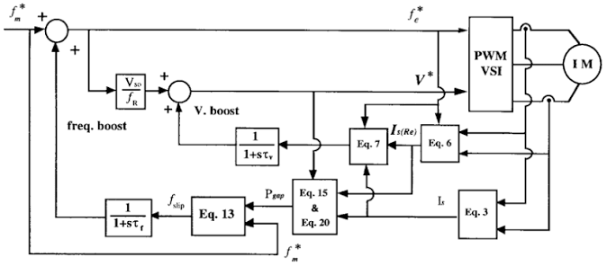
V/F control and vector‑control (also widely‑named field‑oriented control, FOC) represent two fundamentally different ways an AC‑inverter governs motor‑stator current, magnetic flux and output torque. Getting the driving‑mode matched to your mechanical load directly impacts equipment service‑life, energy‑saving returns, production consistency and long‑term operational cost. This practical breakdown walks through working principles, real‑world strengths, obvious drawbacks, side‑by‑side benchmark comparisons and actionable selection advice for all common industrial motor‑load types, helping you make a confident, application‑first VFD parameter choice.
Basic Working Principle Behind V/F Control (Scalar Control)
V/F Control, short for voltage‑per‑hertz scalar control, remains the oldest, most‑used open‑loop motor‑regulation algorithm for general‑purpose variable‑frequency drives. Its core operating logic stays straightforward: the inverter maintains a fixed voltage‑to‑frequency ratio as motor running speed changes.
AC‑induction motor magnetic flux relies on the balance between supply voltage and running frequency. Keeping V/F ratio constant prevents magnetic saturation and flux weakening during speed adjustments. The drive only controls the magnitude of three‑phase output voltage and frequency, and pays no attention to current phase angle, rotor slip status or the independent behaviour of torque‑producing current and magnetizing‑flux current.
A relatable everyday analogy helps technicians quickly grasp its limitation. Running a motor under V/F control feels like driving a car by locking one fixed accelerator position. On flat ground the vehicle holds steady speed. When you hit an uphill slope (sudden added mechanical‑load), the car slows down automatically, with no automatic throttle compensation. The VFD outputs preset voltage and frequency values and will not actively counteract speed drops triggered by load fluctuation.
Standard V/F control works as pure open‑loop operation. No encoder speed‑feedback signal connects back to the frequency converter. The VFD never measures actual rotor rotation speed and can only estimate motor running conditions in a very broad sense. Some advanced VFD firmware adds basic low‑speed torque boost, yet this simple compensation cannot separate flux‑current and torque‑current, leaving fundamental dynamic‑response weaknesses unaddressed.
How Vector Control (Field‑Oriented Control) Operates
Vector‑control marked a major technical leap for alternating‑current motor drives in the late‑1970s. Its core innovation is current decoupling. Using Clarke‑transformation and Park‑transformation mathematics, the VFD splits incoming three‑phase stator current into two independent, orthogonal control components: magnetizing‑flux current and load‑torque current.
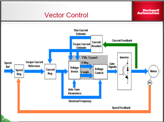
Once these two‑current signals get separated, the frequency drive regulates magnetic‑flux strength and output torque completely independently, identical to the controllability of traditional brushed DC motors. The inverter keeps sampling motor‑stator voltage, running‑current values and, in closed‑loop configurations, encoder rotor‑position data hundreds of times each second. Fast real‑time adjustments counteract load spikes, friction‑resistance and rotor‑slip, so motor‑speed barely drifts even under violent load‑change events.
The vector‑control family contains two primary branches widely available within modern industrial‑grade VFD hardware. Sensor‑less open‑loop vector‑control estimates rotor‑position purely from current and voltage sampling data, requiring zero encoder wiring. Closed‑loop vector‑control installs a shaft encoder for direct rotor‑speed feedback and delivers peak‑level low‑speed torque, precise speed‑holding and fast four‑quadrant torque response.
Returning to the car‑driving comparison, vector‑control acts like an intelligent cruise‑control system. Sensors detect road incline instantly, the engine throttle adjusts up or down without manual input, and travelling‑speed stays consistent uphill, downhill and on flat pavement.
Head‑to‑Head Performance Comparison Between V/F‑Control and Vector‑Control
Below we break down measurable performance gaps, installation requirements and running costs that separate these two motor‑driving‑modes:
- Low‑speed starting torque V/F‑control suffers heavy‑torque fall‑off once motor‑frequency drops below 5Hz. Even with manual torque‑boost tuning, breakaway torque stays limited, and heavy‑starting loads risk motor stalling at startup. Sensor‑less vector‑control delivers up to 150%–200% rated‑motor‑torque under 0.3Hz. Closed‑loop vector‑control supplies full‑rated torque at zero‑speed stand‑still, perfect for hoisting and heavy‑conveyor startup tasksYaskawa.
- Speed‑regulation accuracy Standard open‑loop V/F‑control delivers speed tolerance of ±2%‑3%. Every time load weight changes, running‑speed drifts noticeably. Sensor‑less vector‑control reaches ±0.5% speed precision, and encoder‑based closed‑loop vector‑control achieves ±0.01% high‑end accuracy for spindle and positioning machinery.
- Dynamic load‑response speed V/F‑control reacts slowly to sudden load shocks. If a mixer suddenly thickens raw‑material slurry or a conveyor picks‑up extra cargo, motor‑speed will drop for one‑to‑three seconds before basic torque‑boost kicks‑in. Vector‑control completes torque‑correction in milliseconds, suppressing speed‑dip before operators can observe rotation fluctuation.
- Setup complexity and commissioning work V/F‑control demands minimal parameter‑setup. Users enter motor rated‑voltage, rated‑frequency and run the drive right away. Vector‑control requires an auto‑tune process, where the VFD measures stator‑resistance, rotor‑resistance, inductance values and builds a dedicated mathematical motor‑model. Wrong auto‑tune data directly ruins torque‑stability, so automation technicians spend extra commissioning‑time during installation.
- Hardware requirements and overall‑cost Basic V/F‑operation runs on every entry‑level VFD, with zero‑additional hardware expense. Closed‑loop vector‑control requires shaft‑mounted encoders, encoder‑cable wiring and dedicated encoder‑feedback terminals on your variable‑frequency drive, raising total system investment.
- Multi‑motor driving compatibility One single VFD can run several parallel‑connected induction‑motors under V/F‑control mode. Vector‑control relies on one‑of‑a‑kind motor‑parameter modelling, and one drive can only properly operate one single motor under vector algorithm.
Suitable Industrial‑Load Applications for V/F‑Control
You should stick with V/F‑scalar driving‑mode whenever your mechanical‑load meets these criteria: low‑starting‑torque demand, loose speed‑tolerance requirements and priority on low‑cost, trouble‑free operation. These are the most‑common suitable‑equipment categories:
- Centrifugal fans, air‑blowers and HVAC ventilation‑systems. Fan‑load torque rises with the square of running‑speed and presents minimal resistance during startup. V/F‑control handles energy‑saving speed‑adjustment perfectly well.
- Clean‑water centrifugal‑pumps, waste‑water transfer pumps and circulating‑pump machinery. Most pump‑systems tolerate minor‑speed drift and technicians rarely need heavy torque at ultra‑low running‑speed.
- Light‑duty belt‑conveyors transporting lightweight bulk‑goods, simple agitators with low startup‑resistance and basic cooling‑tower drives.
For all the above‑mentioned general‑purpose loads, switching to vector‑control delivers zero practical‑performance improvement and only adds unnecessary commissioning‑work. Plant‑managers can keep V/F‑mode and cut‑down long‑term maintenance‑labour.
When You Must Choose Vector‑Control for Your Motor‑Load
Switch your VFD parameter setting to vector‑control the moment your machinery faces heavy breakaway‑torque, frequent abrupt‑load changes, zero‑speed holding‑torque and strict‑speed‑stability standards. Here are typical‑use‑cases sorted‑by‑industry sector:
Material‑handling machinery
Overhead travelling‑cranes, warehouse hoists, heavy‑duty mine‑belt conveyors and stacker‑reclaimers. Hoist equipment must hold full‑torque output while stationary to stop cargo slipping, a function V/F‑control can never accomplish.
Machine‑tool and metal‑working equipment
CNC machine‑tool spindles, metal‑rolling mills, lathe feed‑drives and grinding‑heads. Machining‑quality depends entirely on steady spindle‑speed as cutting‑tools bite into hard metal work‑pieces. Speed‑drop leads to uneven surface finish and scrapped work‑parts.
Mixing, kneading and viscous‑material processing
Food‑industry dough‑kneaders, chemical slurry‑mixers and paint‑agitators. Viscous‑material resistance surges sharply the instant mixing‑blades begin turning from rest. Vector‑control supplies instant high‑starting‑torque and prevents motor stall‑out.
Elevators, escalators and passenger vertical‑transport
Lift drives require seamless zero‑speed torque‑support, smooth acceleration‑transition and vibration‑free cabin movement. Closed‑loop vector‑control with encoder feedback counts as the industry‑wide standard.
Winding and unwinding processing‑machines
Paper‑making machinery, textile yarn‑winder and plastic‑film processing‑equipment. Constant‑tension control needs independent torque‑regulation, a feature exclusive to vector‑control algorithms.
Common Mistakes Engineers Make When Selecting Motor‑Driving‑Mode
Years of VFD‑commissioning experience expose several recurring‑missteps among automation‑staff, and you can avoid these traps on‑site:
First, many technicians leave factory‑default V/F‑control enabled for heavy‑start‑up loads, then waste hours troubleshooting motor stalling at low‑frequency. The fix is straightforward: run motor auto‑tune and switch over to sensor‑less vector‑control.
Second, some machine‑builders blindly activate closed‑loop vector‑control and fit expensive encoders for simple fan‑and‑pump‑loads. That decision inflates material‑cost, lengthens wiring‑time and introduces new potential‑failure points such as damaged encoder‑cables.
Third, operators attempt to run multiple parallel‑motors under vector‑control mode. Each induction‑motor carries unique winding‑resistance parameters, and the single motor‑model inside your VFD cannot match several motors at once. Parallel multi‑motor installations always use V/F scalar‑mode.
Final Checklist to Pick Between Vector‑Control and V/F‑Control
Run through this quick checklist before locking your VFD drive‑mode setting:
- Does my machinery need strong torque below 5Hz or stationary‑holding torque? → Choose vector‑control
- Can I accept running‑speed fluctuation of 2–3% during load‑shifts? → Stick to V/F‑Control
- Will the motor confront sudden, violent load‑spikes in normal‑operation? → Choose vector‑control
- Does one inverter drive more than one induction‑motor? → Stick to V/F‑Control
- Is my equipment a fan, centrifugal‑pump or low‑resistance auxiliary‑device? → Stick to V/F‑Control
- Am I running winding‑machinery, CNC‑spindles, hoists and heavy‑duty processing‑mixers? → Choose vector‑control