
A short-circuit inside a medium-voltage converter can ruin an IGBT within microseconds. Fast-rising fault current plus power-loop stray inductance creates dangerous Vce overshoot. Standard hard turn-off often worsens this risk — this is where IGBT gate voltage reduction protection shines.
As a robust short-circuit protection strategy, IGBT gate voltage reduction protection avoids instant gate shutdown. The driver lowers the gate voltage to clamp short-circuit current and slow di/dt. It extends fault detection time, cuts electrical stress and protects IGBTs from breakdown.
In this article, explore how IGBT gate voltage reduction protection works, its advantages over hard turn-off, and use cases for medium-voltage drives in mining, oil & gas and wind power.
Why Short-Circuit Protection Is Critical in Medium-Voltage Converters
Medium-voltage converters operate at 660V, 1140V, 3.3kV, 6kV, and even 10kV. At these levels, the consequences of a fault are severe.
When a short-circuit happens, several things occur at once:
- The collector current (Ic) rises sharply.
- The rate of current change (di/dt) becomes extremely high.
- The loop stray inductance (L) produces a voltage drop described by V = L × di/dt.
- This voltage adds to the collector-emitter voltage (Vce) and can exceed the device rating.
The result is a Vce spike that punches through the IGBT. Even a single hard turn-off event under heavy current can cause permanent damage.
The core challenge is simple. You must turn the device off, but you cannot do it too aggressively. Otherwise the protection itself becomes the cause of failure.
That is the exact problem that gate voltage reduction solves.
What Is IGBT Gate Voltage Reduction Protection?
IGBT gate voltage reduction protection is a short-circuit protection strategy for IGBT gate drivers. The driver detects a fault, then reduces the gate-emitter voltage (Vge) from the normal positive drive level, such as +15V, to a lower positive level, such as +8V to +10V.
The key point is that the driver does not turn the IGBT off right away. Instead, it holds the device in a partially conducting state for a short window.
This approach is also known by other names in the industry:
- Reduced gate drive protection
- Gate clamping protection
- Soft turn-off with reduced gate voltage
Whatever you call it, the principle is the same. Lower the gate voltage first, limit the damage, then decide what to do next.
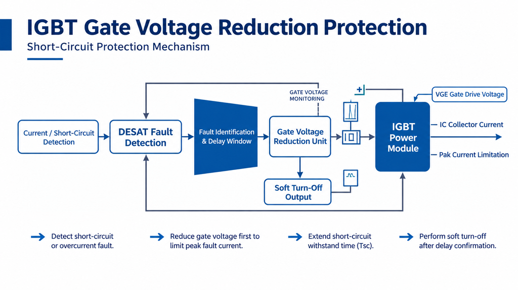
How Gate Voltage Reduction Works
The sequence follows a clear and repeatable pattern.
Step 1: Fault Detection
The driver uses a DESAT (desaturation) detection circuit. During normal conduction, the IGBT has a low collector-emitter voltage. Under a short-circuit, the device desaturates and Vce rises sharply.
The DESAT circuit senses this rise and triggers a fault signal. This detection happens in about 1 to 10 microseconds.
Step 2: Gate Voltage Reduction
Once the fault is detected, the driver pulls Vge down to a lower positive value. The IGBT stays on, but its transconductance drops.
This produces two immediate effects:
- The short-circuit current is clamped to a lower level.
- The current slew rate (di/dt) is slowed down.
Both effects reduce the mechanical and electrical stress on the device.
Step 3: Fault Confirmation and Blanking Time
The driver keeps the reduced gate voltage for a preset time. This is the blanking window. During this window, the system checks whether the fault is real.
- If the fault disappears, the drive can recover and return to normal operation.
- If the fault remains, the system proceeds to the next step.
Step 4: Turn-Off
If the fault persists beyond the blanking time, the driver completes the turn-off. Because the current was already limited, the final turn-off is much safer.
This multi-step logic is what makes the protection intelligent rather than reactive.
Hard Turn-Off vs. Soft Turn-Off vs. Gate Voltage Reduction
To understand the value of gate reduction, compare it with the alternatives.
表格
| Protection Method | Action on Fault | Peak Current | Vce Spike | Complexity | Best For |
|---|---|---|---|---|---|
| Hard turn-off | Gate pulled negative immediately | Very high | Very high | Low | Low-power, low-inductance loops |
| Soft turn-off | Gate discharged slowly through a resistor | High | Moderate | Medium | Medium-power loops |
| Gate voltage reduction | Gate lowered, held, then turned off | Limited | Low | High | High-power, high-inductance loops |
Hard turn-off reacts fastest. But in a large converter, the Vce spike it creates can be lethal. Soft turn-off reduces the spike but does little to clamp the peak current.
Gate voltage reduction addresses both problems. It clamps the current and suppresses the voltage spike. This is why it is the preferred choice for medium and high-voltage converters.
Key Benefits of Gate Voltage Reduction Protection
1. Active Current Limiting
By reducing the gate voltage, the driver clamps the collector current. This suppresses the peak short-circuit current before it can damage the device.
2. Extended Short-Circuit Withstand Time
Lower current stress and lower power dissipation extend the IGBT short-circuit withstand time (Tsc). This gives the gate driver a real detection window. Without it, the device may fail before the protection logic can act.
3. Turn-Off Overvoltage Suppression
Avoiding a hard turn-off under heavy current reduces the risk of a Vce spike caused by parasitic inductance. This directly prevents overvoltage breakdown.
4. Intelligent Fault Handling
The driver can recover from transient disturbances according to the protection strategy. Only a confirmed short-circuit triggers a soft turn-off. This reduces nuisance trips and improves system reliability.
Where to Apply Gate Voltage Reduction
This protection is most valuable in high-power, high-inductance applications. Common examples include:
- Medium-voltage mining drives — belt conveyors, mine hoists, and scraper conveyors
- Oil & gas equipment — pumps, compressors, and drilling drives
- Wind power converters — turbine and grid-side converters
- Energy storage PCS — bidirectional power conversion systems
- Industrial VFDs — variable frequency drives above 660V
In all these cases, the power loop carries high stray inductance. Hard turn-off would be dangerous. Gate voltage reduction keeps the device alive through a fault.
Design Considerations for Implementation
If you are evaluating this protection for your own system, keep these points in mind.
Gate Drive Capability
Your driver must support two gate voltage levels. Not all drivers can do this. Check whether the driver IC offers a reduced gate voltage mode.
Blanking Time
The reduced gate voltage phase cannot last forever. The IGBT still dissipates power while partially conducting. Keep the blanking time within the device’s short-circuit withstand capability.
Detection Speed
A faster DESAT detection leaves less time for the fault current to build. Faster detection means less stress on the device.
System Coordination
The protection works best when the driver, the controller, and the power stage are designed together. A sudden load change, for example, should be distinguished from a true short-circuit.
How Sunsin Implements Gate Voltage Reduction
At Sunsin, short-circuit ruggedness is a design priority for every medium-voltage drive. Our medium-voltage VFDs and three-level converters combine DESAT detection with gate voltage reduction to protect IGBTs across 660V to 10kV systems.
The result is a converter that survives real-world faults in mining, oil & gas, and wind applications, while maintaining high reliability and uptime. Field experience shows that a well-designed protection scheme prevents the majority of device failures.
Frequently Asked Questions
What is IGBT gate voltage reduction protection? It is a short-circuit protection method where the driver lowers the gate voltage after detecting a fault, instead of turning the IGBT off immediately. This limits current and suppresses voltage spikes.
Why not use hard turn-off? Hard turn-off reacts fast but creates a large Vce spike from the loop inductance. In high-power converters, this spike can destroy the IGBT.
Does gate voltage reduction damage the IGBT? No. The reduced gate phase is kept short, within the device withstand time, so the added stress stays within safe limits.
Where is this protection most useful? In medium and high-voltage converters with high stray inductance, such as mining drives, wind converters, and energy storage systems.
Conclusion
Short-circuit protection is not just about reacting. It is about reacting the right way. IGBT gate voltage reduction protection lowers the gate voltage on fault, clamps the peak current, extends the short-circuit withstand time, and suppresses the Vce spike. This combination boosts the short-circuit ruggedness of medium-voltage converters and keeps expensive power devices alive.
Whether you design drives or specify them, this protection should be high on your checklist. In high-power, high-inductance systems, it is often the difference between a nuisance event and a catastrophic failure.