
RS485 communication issues are among the most common and disruptive faults in daily VFD operation. In automated production lines, HVAC systems, water pump group control setups, and PLC-VFD linkage architectures, unstable or broken RS485 communication creates real operational headaches. Engineers often face unresponsive VFD speed commands, inaccurate real-time data feedback, random drive offline alarms, and unexpected production halts.
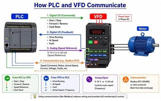
Most on-site technicians fix these issues with quick workarounds—restarting the VFD, unplugging and reconnecting cables, or resetting parameters. Yet the problem always comes back after hours or days of runtime. The truth is, intermittent or permanent RS485 communication failure rarely happens randomly. It stems from improper field wiring, mismatched terminal resistance, conflicting communication parameters, unsuppressed electromagnetic interference, or aging hardware components.
This practical, field-tuned guide walks you through complete VFD RS485 communication troubleshooting steps. We cover real-world failure symptoms, systematic diagnosis logic, root-cause analysis, and reliable fixes for Modbus RS485 communication errors between PLC, HMI, and variable frequency drives. By following this workflow, you can permanently resolve communication faults and stabilize your industrial automation system long-term.
Typical Signs of VFD RS485 Communication Failure
Before jumping into repairs, you can quickly narrow down the fault source by observing device behavior. Most RS485 communication problems fall into three obvious on-site manifestations:
1. Intermittent offline and unstable connection The VFD works perfectly right after startup, responds smoothly to commands, and uploads data normally. But after 10 to 30 minutes of continuous operation, it suddenly goes offline. The master station (PLC or HMI) pops up communication timeout alerts, and the VFD no longer accepts speed adjustment or start-stop instructions. This is almost always caused by electromagnetic interference or incorrect terminal resistor settings.
2. One-way communication abnormality This is a confusing but common scenario. The PLC can successfully send start, stop, and speed commands to control the VFD, but it cannot read feedback data including running frequency, motor current, load rate, and fault codes. In rare cases, the master station can receive data but fails to control the drive. This issue mainly comes from inconsistent communication parameters between master and slave devices.
3. Complete communication failure on power-up From the moment the system powers on, there is zero data interaction between the PLC and VFD. The system keeps reporting communication alarms with no response at all. This usually results from reversed wiring, damaged communication ports, or duplicate Modbus address conflicts.
Step 1: Inspect Field Wiring and Cable Installation
Based on actual maintenance statistics, over 60% of VFD RS485 communication faults originate from non-standard field wiring. Many temporary construction habits work for short-term testing but cause chronic instability in long-term operation.
First, double-check A and B signal polarity. RS485 relies on differential signal transmission, which requires strict correspondence: the master station A terminal connects to VFD 485+ (A), and the master station B terminal connects to VFD 485- (B). Reversed A/B wiring will not burn the port, but it directly triggers signal parsing failure and unstable connection. Note that some VFD brands mark terminals as D+ and D-, which fully correspond to A and B signal lines.
Second, confirm you are using the correct cable type. Standard shielded twisted pair cable is mandatory for VFD RS485 communication. Ordinary parallel wires lack anti-interference capability and cannot resist high-frequency noise generated by VFD inverters, contactors, and nearby high-power equipment. For field layout, separate communication cables from high-voltage power cables. Keep a physical distance above 20cm and avoid laying them in the same cable tray to prevent signal distortion.
Third, standardize shielding layer grounding. The cable shielding layer must be grounded only at the master station end. Never ground both ends. Dual-end grounding creates a ground loop, induces stray current on the shielding layer, and causes continuous signal interference—this is a top hidden cause of intermittent offline faults that are hard to reproduce and troubleshoot.
Step 2: Correct RS485 Terminal Resistance Matching
Signal reflection and attenuation caused by mismatched terminal resistance is the leading cause of sporadic, hard-to-locate communication failures. The RS485 bus requires impedance matching to ensure complete signal transmission without reflection noise.
The industry standard requires a 120Ω terminal resistor at the head and tail of the entire bus network. For a single-VFD system, simply enable the VFD’s built-in terminal resistance or install an external 120Ω resistor between the A and B terminals. For multi-VFD parallel networks, only the first master station and the last slave VFD activate terminal resistance. All intermediate drives must keep this function turned off.
A frequent on-site mistake is enabling terminal resistance on every VFD in the loop. This overloading drags down bus impedance, aggravates signal attenuation, and triggers continuous timeouts. After adjustment, use a multimeter to test resistance between A and B. A normal reading between 60Ω and 120Ω confirms qualified matching.
Step 3: Fully Align Master and Slave Communication Parameters
Parameter mismatch ranks second among all RS485 fault causes. Every communication parameter on the PLC master station and VFD slave station must be identical. Any single inconsistent setting will lead to data parsing errors and communication breakdowns.
Modbus slave address is the first item to verify. Each VFD on the bus needs a unique independent address (1–247). Repeated addresses cause bus data collision, leading to random disconnection and unordered signal feedback. Always check and unify addresses during batch VFD networking.
Baud rate, data bits, stop bits, and parity mode must be fully consistent. 9600bps and 19200bps are the most common baud rates for industrial VFDs. Higher baud rates boost refresh speed but weaken anti-interference ability, while lower rates improve stability but slow down data response. In most industrial scenarios, 8 data bits, 1 stop bit, and even/no parity check form the most stable combination.
Also confirm the protocol type. Almost all industrial VFDs adopt Modbus RTU, not Modbus ASCII. Mismatched protocol types result in zero communication response. Meanwhile, ensure the VFD control source is set to RS485 communication mode, not local panel or terminal manual control.
Step 4: Eliminate On-Site Electromagnetic Interference
Industrial workshops are filled with interference sources: VFD high-frequency switching, motor startup impact, contactor action, and welding equipment radiation. These noises pollute the RS485 differential signal and cause data garbling and jitter. If wiring and parameters are correct but faults persist, interference suppression is the key solution.
Start with reliable equipment grounding. A qualified VFD ground wire stabilizes signal reference potential and releases high-frequency harmonic noise effectively. Keep grounding resistance below 4Ω and avoid shared grounding with high-power motors.
For severely interfered sites, install magnetic rings on both ends of the RS485 cable or add input/output filter reactors to the VFD power terminal. These accessories suppress high-frequency harmonics and greatly improve communication stability in complex electromagnetic environments.
Step 5: Check for Hardware Damage and Port Aging
If all software settings, wiring, and interference processing fail to solve the problem, hardware damage is highly suspected. Long-term operation in high-temperature, humid, and dusty environments accelerates the aging of VFD RS485 communication chips and ports.
You can use the replacement testing method for quick verification. Swap in a new communication cable and a known good VFD for connection. If the system recovers, the original VFD communication port is damaged. Static shock and on-site voltage surges also commonly burn out RS485 chips. For such cases, installing an external RS485 expansion module is a cost-effective alternative to replacing the entire drive.
Most Common On-Site Mistakes to Avoid
Most recurring communication faults come from habitual operational errors. Technicians often adjust baud rates blindly to pursue faster data transmission without matching the master station parameters. Many also enable terminal resistance on all parallel VFDs, overloading the bus signal. In addition, using ordinary non-shielded cables for long-distance communication is a classic mistake that leads to hard-to-reproduce intermittent faults.
Final Conclusion
VFD RS485 communication failure is not a complex technical fault, but it requires systematic, step-by-step troubleshooting instead of blind restarting and resetting. The vast majority of problems are not caused by equipment damage, but by non-standard construction, mismatched resistance, inconsistent parameters, and uncontrolled field interference.
Following the standard workflow—wiring inspection, resistance matching, parameter alignment, interference elimination, and hardware verification—can solve almost all RS485 and Modbus communication errors. Standardizing early installation and regular maintenance is always more efficient than troubleshooting after failures, helping automation systems maintain long-term stable and low-fault operation.